Real assessment example
What a professional yard drainage assessment looks like
Two problem areas around one Dallas–Fort Worth home were documented, explained and organized into one connected drainage plan.
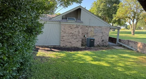
Start with the water path
A useful estimate should explain more than where a drain might go.
A good yard drainage assessment identifies where the water comes from, why it remains, how the surrounding grade controls its movement and where the collected water can be discharged. In this example, the property had two visibly different problem areas, but both lacked a reliable route away from the house.
The proposed layout treated the property as a connected system instead of recommending isolated products. Surface grading, catch basins, roof runoff, solid pipe and the existing outlet all had to work together.
Problem area 1
Water remaining near the foundation
The first area already had catch basins, but their location and the surrounding surface did not create dependable drainage away from the house.
What the assessment found
The existing collection points were too close to the foundation to establish a useful surface slope away from the structure. The ground was uneven, and runoff from the surrounding property did not have a consistent path through the area.
Roof water was also being released from the downspout directly onto the ground and nearby paved surfaces. During rain, that concentrated flow could repeatedly saturate soil beside the house instead of entering a controlled underground line.
The puddle was the visible symptom. The larger concern was repeated moisture beside the foundation, especially where North Texas soil can expand, shrink and erode as its moisture content changes.
Proposed Area 1 scope
Move, collect and convey
- Position three 12-by-12-inch catch basins approximately two to three feet from the foundation.
- Connect one 4-inch downspout directly to the underground drainage system.
- Use solid 4-inch pipe for the conveyance route.
- Remove soil from the high section where needed and regrade away from the house.
- Maintain approximately 1% fall toward the existing outlet, subject to field verification.


Problem area 2
No consistent slope or functional drainage path
The second area had no dependable collection points, controlled low line or underground route, so water entering the space had nowhere reliable to go.


Why one drain would not be enough
Water must first be directed to a collection point. A catch basin placed in an arbitrary location cannot correct an uneven surface that sends water in several directions. The buried line also needs continuous fall and a suitable outlet.
In this area, roof runoff and runoff entering from beyond the immediate yard added water to an already flat, confined space. Without coordinated grading, collection and conveyance, standing water could continue even after a single inlet was installed.
Proposed Area 2 scope
Create a controlled center route
- Install six 9-by-9-inch catch basins along a controlled central low point.
- Connect two 4-inch downspouts directly to the underground system.
- Run approximately 145 linear feet of solid 4-inch pipe to the existing drainage system.
- Regrade the area so the foundation and fence sides remain higher than the center route.
- Create approximately 1% fall toward the basins where field conditions allow.


Why the scope was not reduced
The simplest complete solution is not always the smallest list of materials.
Several approaches were considered while the estimate was being prepared. A more expensive alternative was removed because it did not offer a better practical result. Reducing the remaining scope was not recommended because each component had a separate job.
Grading directs water. Catch basins collect it. Downspout connections control concentrated roof runoff. Solid pipe carries the collected water, and the outlet completes the route. Removing one of those pieces could leave part of the original problem unresolved.
What this example demonstrates
Similar puddles can require different drainage details.
Trace every input
Roof discharge, neighboring runoff, pavement and natural surface flow can all contribute water to the same low area.
Measure the grade
Collection points work only when the surrounding surface and underground line can move water toward them and onward.
Confirm the outlet
A proposed drain is incomplete until the full route reaches a suitable, maintainable discharge point.
If water remains beside your foundation, between homes, around a patio or in the same low part of the yard after each rain, an on-site assessment can identify the likely cause and show how the proposed system is intended to function before installation begins.
Need a property-specific plan?
See what is included in an on-site drainage assessment.
Learn about our property drainage assessmentsThis page presents an example of a completed drainage assessment and proposed layout. It does not represent a completed installation. Client-identifying information and pricing have been removed. Installation-reference photographs shown in the original assessment are labeled in their captions.